KNX
The KNX I/O Server provides for the control of a KNX installation compliant with the KNX Standard version 2.0.
The communication between HSYCO and the KNX network must employ a KNXnet/IP gateway supporting the Tunneling service.
The KNX framework must be programmed to work properly using the ETS tool.
Each defined KNX group is seen as a datapoint whose value is formatted with respect to its DPT type. Supported DPT types range from DPT 1 to DPT 18. Moreover, it is possible to have virtual datapoints that link a set of datapoints used for the control of devices such as lights, dimmers, automations and thermostats which require several KNX groups for commands and feedback.
HSYCO Configuration
Options
| ID | Default | Values | Description |
|---|---|---|---|
| startupevents | false | true | generate IO events also during the driver’s start-up phase |
| false | start generating events only after HSYCO is aligned with the current status of the system | ||
| discovery | true | true | automatically create the list of all detected datapoints with type DPT 1 and the defined virtual datapoints in the systemtopo.txt file |
| false | auto-detect for devices is disabled | ||
| fromevents | false | true | generate events for commands sent on the KNX BUS reporting the source address and the value of the command |
| false | disable command events | ||
| readaftercommand | false | true | force the driver to read the value of a datapoint after a command is sent to it |
| false | the driver will assume that commands detected on the BUS are always successful, thus no re-reading is performed to set the value of a datapoint | ||
| localport | <port_number> | the port number used locally by HSYCO to communicate with the KNXnet/IP gateway. This option might be necessary when employing network address translation (NAT) |
Datapoints Declaration
It is required to provide the I/O Server with the KNX framework configuration. To this end, the KNX Utility provides a graphical interface to import ETS4 project files and to configure the datapoints.
It is also possible to manually define the datapoints in the knxtopo.txt file.
Datapoints
| ID | Value | R/W | Description |
|---|---|---|---|
| connection | online | R | connection established with the board |
| offline | R | HSYCO can't connect to the board | |
| pinmode | <pin>,input | W | execute the pinMode() function, configuring the pin <pin> as INPUT, OUTPUT or INPUT_PULLUP
|
| <pin>,output | |||
| <pin>,input_pullup | |||
| digitalwrite | <pin>,high | W | execute the digitalWrite() function, setting the pin <pin> to high (5V or 3.3V) or low (0V)
|
| <pin>,low | |||
| digitalread | <pin> | W | execute the digitalRead() function, reading the value of pin <pin>
|
| analogwrite | <pin>,<value> | W | execute the analogWrite() function, setting the pin <pin> to a PWM output with duty cycle equal to <value>; the value must be between 0 (always off) and 255 (always on)
|
| analogread | <pin> | W | execute the analogRead() function, reading the value of pin <pin>
|
| pin.<n> | 0 | R | pin <n> is low |
| W | execute the digitalWrite() function, setting the digital pin <n> to low (0V)
equal to digitalwrite = <n>,low | ||
| 1 | R | pin <n> is high | |
| W | execute the digitalWrite() function, setting the digital pin <n> to high (5V or 3.3V)
equal to digitalwrite = <n>,high | ||
| pin.a<n> | <value> | R | analog pin <n> is set to duty cycle equal to <value> |
| W | execute the analogWrite() function, setting the analog pin <n> to a PWM output with duty cycle equal to <value>; the value must be between 0 (always off) and 255 (always on)
equal to analogwrite = a<n>,<value> | ||
| pin.dac<n> | <value> | R | DAC pin <n> is set to <value> |
| W | execute the analogWrite() function, setting the DAC pin <n> to <value>
equal to analogwrite = dac<n>,<value> | ||
| <custom_name> | <value> | R | the ioSet(<custom_name>, <value>) method was called from the Arduino sketch |
| W | if a callback function is defined in the Arduino sketch, this function is called passing <custom_name> and <value> as parameters. The parameters cannot contain the 0x0a, 0xff, or '=' characters |
Pins syntax
The naming convention HSYCO uses for the pins corresponds to the one used by Arduino.
Digital pins are numbered from 0 up, with no prefix.
Analog pins start with the "a" prefix, like "a0", "a1" etc. (all lowercase).
The DAC analog out pins in Arduino DUE are "dac0" and "dac1" (all lowercase).
UI Objects
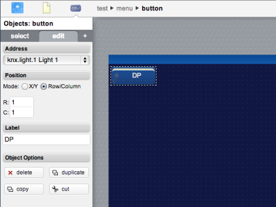
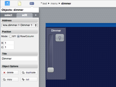
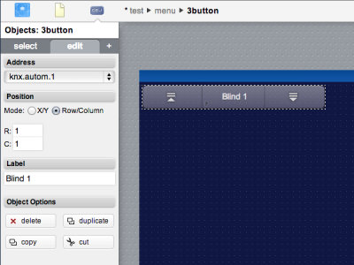
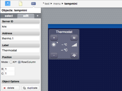
All the DPT 1 datapoints and virtual datapoints that have been defined are automatically listed in the Project Editor. DPT 1 datapoints and lights can be directly linked to a "button" object, dimmers to a "button" or a "dimmer" object, automations to "button" or "3button" objects and thermostats can be controlled though a "tempmini" object.


