Hephais
The SD3 HEPHAIS 1600 is a multi-zones fire panel. The integration with HSYCO can be accomplished via a standard Modbus RTU slave interface. This I/O Server requires HEPHAIS 1600 with protocol modbus JBUS V0.13
Contents
Modbus Connections
The HEPHAIS 1600 has a Modbus interface. The default connection parameters are: Modbus address: 1 (can be set to 1 - 247) communication parameters: 9600 bps, 8 bits, 1 stop bit, no parity. Refer to the HEPHAIS 1600 manuals for installation, wiring and power supply requirements.
The modbus wires terminal is the “Block 11”. Modbus type is RS-422/JBUS (IN+/OUT+, IN-/OUT-, GND).
The Modbus-TCP/IP gateway used for the connection must support RS-422/JBUS.
HSYCO Configuration
Options
| ID | Default | Values | Description |
|---|---|---|---|
| gui | true | true | enable support for the UI object, UISET actions and USER commands |
| false | disable UI support | ||
| startupevents | false | true | generate IO events also during the driver’s start-up phase |
| false | start generating events only after HSYCO is aligned with the current status of the system | ||
| address | 1 | 1...247 | the panel's Modbus address |
| pollinterval | 3 | n > 0 | the data acquisition interval, in seconds |
| maxpoint | m4.l2.200 | point id | id of the highest point used on the panel. The number after ‘m’ represents the number of the module, the number after ‘l’ represents the loop number of the module and the last number is the address of the point within the loop. Acceptable values range from “m1.l1.1” to “m9.l2.200” |
| hysteresis | 0 | <n> | if different than zero, the datapoints’ values are checked <n> times before being set. Setting this option to a value different from zero will decrease the responsiveness of the driver |
hephais.ini
The hephais.ini file is a specific configuration file located in the root directory. Here you can define the names of the users so that they will be automatically added to the user interface. Add a new line for each user using this format:
<io_server_id>.m<m>.l<l>.<addr>.name = <name>
Add a new line to specify the zone the point belongs using this format: <io_server_id>.m<m>.l<l>.<addr>.zone = <name>
Add a new line to define the name of a zone using this format: <io_server_id>.z<n>.name = <name>
For instance:
	fire.m1.l1.1.name = Entrance
	fire.m1.l1.1.zone = 1
	fire.m1.l1.2.name = Corridor
	fire.m1.l1.2.zone = 2

	fire.z1.name = Zone 1
	fire.z2.name = Zone 2
Datapoints
| ID | Value | R/W | Description |
|---|---|---|---|
| connection | online | R | connection established |
| offline | R | HSYCO can't connect to the panel | |
| alarm | 1 | R | fire panel in alarm |
| 0 | R | no alarm | |
| fault | 1 | R | fire panel fault |
| 0 | R | no fault | |
| oos | 1 | R | at least one point out of service |
| 0 | R | no point out of service | |
| test | 1 | R | at least one zone in test mode |
| 0 | R | no zone in test mode | |
| error.sys | 1 | R | system fault |
| 0 | R | no system fault | |
| prealarm | 1 | R | fire panel in pre-alarm |
| 0 | R | no pre-alarm | |
| alarm.tec | 1 | R | fire panel in technical alarm |
| 0 | R | no technical alarm | |
| sound | 1 | R | H.S. speaker active |
| 0 | R | H.S. speaker not active | |
| error.com | 1 | R | fire panel communication error |
| 0 | R | no fire panel communication error | |
| error.battery | 1 | R | fire panel battery error |
| 0 | R | no fire panel battery error | |
| error.sector | 1 | R | fire panel sector fault |
| 0 | R | no fire panel sector fault | |
| z<n>.name | <text> | R | name assigned to zone <n> |
| z<n>.alarm | 1 | R | fire panel in alarm |
| 0 | R | no alarm | |
| z<n>.oos | 1 | R | fire panel in alarm |
| 0 | R | no alarm | |
| z<n>.fault | 1 | R | fire panel in alarm |
| 0 | R | no alarm | |
| z<n>.test | 1 | R | fire panel in alarm |
| 0 | R | no alarm | |
| m<m>.l<l>.<n>.name | <text> | R | name assigned to point P of module <m> in loop <l> |
| m<m>.l<l>.<n>.oos | 1 | R | fire panel in alarm |
| 0 | R | no alarm | |
| m<m>.l<l>.<n>.alarm | 1 | R | fire panel in alarm |
| 0 | R | no alarm | |
| m<m>.l<l>.<n>.fault | 1 | R | fire panel in alarm |
| 0 | R | no alarm | |
| m<m>.l<l>.<n>.alarm.test | 1 | R | fire panel in alarm |
| 0 | R | no alarm |
User Interface
CSx75 Object
The user interface for the Aritech CSx75 multi-area security system.
The CSx75 object is listed in the Project Editor’s new object list only when at least one Aritech CSx75 I/O Server is defined.
Parameters
- server id: the server ID
- partition: partition number of the Aritech CSx75 multi-area security system
- position: the object's position. Use the pixels or rows and columns coordinates format
Syntax
(csx75 <server id>; <partition>; <position>)
E.g.
(csx75 serverid; partition; x10y20)
UISET Actions
| ID | Attribute | Set to | |
|---|---|---|---|
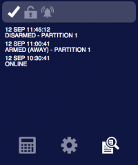
| log | value | latest security log lines (as many as specified by the 'logsize' option) | |
| log0 | value | latest line of the security log when a new entry is added, set back to blank after a short period | |
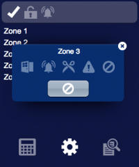
| z<n>.name | value | name assigned to zone <n> (base or double) or its number if no name is defined | |
| p<n>.last.user | value | ID of the last user who logged in on partition <n> | |
| user<n>.name | value | name assigned to user <n> | |
| connection.label | visible | true | when datapoint connection = offline |
| false | when datapoint connection = online | ||
| p<n>.armed.0.label | visible | true | when partition <n> is disarmed |
| false | when partition <n> is armed | ||
| p<n>.armed.away.label | visible | true | when partition <n> is armed in "away" mode |
| false | when partition <n> is not armed in "away" mode | ||
| p<n>.armed.stay.label | visible | true | when partition <n> is armed in "stay" mode |
| false | when partition <n> is not armed in "stay" mode | ||
| <datapoint_id>.1.label | visible | true | when datapoint with ID <datapoint_id> has value '1' |
| false | when datapoint with ID <datapoint_id> has value '0' | ||
| <datapoint_id>.0.label | visible | true | when datapoint with ID <datapoint_id> has value '0' |
| false | when datapoint with ID <datapoint_id> has value '1' | ||
USER Commands
| Name | Param | Action |
|---|---|---|
| armed[Note] | 0 | disarm all partitions |
| stay | arm all partitions in "stay" mode | |
| away | arm all partitions in "away" mode | |
| auto | initiate auto-arm on all partitions | |
| p<n>.armed[Note] | 0 | disarm partition <n> |
| stay | arm partition <n> in "stay" mode | |
| away | arm partition <n> in "away" mode | |
| auto | initiate auto-arm on partition <n> | |
| p<n>.cancel[Note] | 1 | issue cancel command on partition <n> |
| p<n>.buzzer | 1 | start buzzer on partition <n> |
| p<n>.exit.silent | 1 | enable silent exit for this arm cycle on partition <n> |
| Z<n>.bypassed | toggle | toggle the bypass status of zone <n> |
| p<n>.chime.mode | toggle | toggle chime mode on partition <n> |
| walk.test[Note] | 0 | stop walk-test mode |
| 1 | start walk-test mode | |
| aux1 p<n>.aux1 |
1 | activate auxiliary function 1 |
| aux2 p<n>.aux2 |
1 | activate auxiliary function 2 |
| panic p<n>.panic |
fire | issue the fire panic command |
| medical | issue the medical panic command | |
| police | issue the police panic command
| |
| smoke p<n>.smoke |
reset | smoke detector reset |
| test p<n>.test |
1 | perform test |
| command | restart | restarts the driver |
- Note
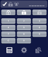
- To perform this operation it is necessary to enter the user code first. To enter the user code through the user interface use user buttons to create a virtual keypad and assign them name and param values according to this table:
| Name | Param | Action |
|---|---|---|
| digit | {0 ... 9} | append the specified digit to the entered user code |
| c | delete the last entered digit |
To visualize the number of entered digits use 4 or 6 text objects (depending on the number of digits used for user codes) and set their IDs to:
| ID | Description |
|---|---|
| pin.<n> (0 ≤ <n> ≤ 5) |
shows the character '*' when the corresponding digit has been entered, shows '_' otherwise |
The entered code will be cleared after a short period of inactivity.


