MPower
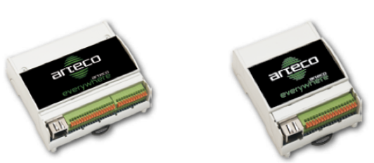
Arteco Everywhere is a general purpose digital input-output Ethernet controller.
It is available in two versions, a 4 inputs, 4 outputs module, and an 8 inputs 8 outputs module.
The ARTECOIO I/O Server in HSYCO creates a data point representation that you can use in the EVENTS language and Java to read the input pins and control the outputs. It also automatically allows you to create control objects for the Web user interface.
Contents
HSYCO Configuration
Add an ARTECOIO I/O Server in the I/O Servers section of the Settings and set its parameters:
Communication
- IP Address: host name or IP address of the Arteco module (the default address is 192.168.10.96)
- IP Port: TCP/IP port to use, leave blank to use default port 80
- User: username, leave blank to use default username "admin"
- Password: password, leave blank to use default password "arteco".
High Availability
- Shutdown when inactive: defaults to false.
Options
| ID | Default | Values | Description |
|---|---|---|---|
| startupevents | false | true | generate IO events also during the driver’s start-up phase |
| false | start generating events only after HSYCO is aligned with the current status of the system | ||
| inputdiscovery | false | true | automatically creates the list of all inputs in the systemtopo.txt file. Should be enabled to allow the automatic update of (button) objects’ states |
| false | auto-detect for input devices is disabled | ||
| outputdiscovery | false | true | automatically creates the list of all outputs in the systemtopo.txt file. Should be enabled to allow the automatic update of (button) objects’ states |
| false | auto-detect for output devices is disabled | ||
| inputs | 8 | 0 ... 8 | use input pins from 0 to the specified value |
| outputs | 8 | 0 ... 8 | use output pins from 0 to the specified value |
Datapoints
The data points associated to the input pins are named “i0” to “i7”. The data points associated to the output pins are named “o0” to “o7”.
The I/O Server generates asynchronous events based on the status of the Arteco module’s input and output pins. The output data points can be written to control the output pins.
| ID | Value | R/W | Description |
|---|---|---|---|
| connection | online | R | connection established |
| offline | R | HSYCO can't connect to the device | |
| i<n> | 0 | R | input <n> is low |
| 1 | R | input <n> is high | |
| o<n> | 0 | R | output <n> is low |
| W | set output <n> to off | ||
| 1 | R | output <n> is high | |
| W | set output <n> to on | ||
| flip | W | invert the status of output <n> | |
| blink | W | continuously blink output <n> | |
| pulse | W | set output <n> to on, then off after 1 sec. |
User Interface
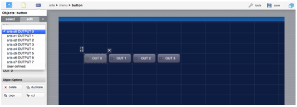
When using the default settings of the Arteco I/O Server, all output pins are available in the Project Editor and can be easily associated to any control button of the Web interface.
You can also set the inputdiscovery option in order to associate control buttons to the module’s inputs: the control buttons will show the input status, and have no effect when pressed.
Release Notes
3.3.0
- initial release
ARTECO is a registered trademark of Arteco Srl.

