Difference between revisions of "IonoPiMax"
Jump to navigation
Jump to search
| Line 31: | Line 31: | ||
|rowspan="2"|startupevents | |rowspan="2"|startupevents | ||
| − | |rowspan="2"| | + | |rowspan="2"|false |
|true | |true | ||
|generate IO events also during the driver’s start-up phase | |generate IO events also during the driver’s start-up phase | ||
| Line 40: | Line 40: | ||
|- | |- | ||
| − | | | + | |pollinterval |
| − | | | + | |250 |
| − | | | + | |10 <= n <= 30000 |
| − | + | |the data acquisition interval, in milliseconds | |
| − | |||
| − | |||
| − | |||
| − | |||
| − | |||
| − | |||
| − | |||
| − | |||
| − | |||
| − | |||
| − | |||
| − | |||
| − | |||
| − | |||
| − | |||
| − | |||
| − | |||
| − | |||
| − | | | ||
| − | |||
| − | |||
| − | |||
| − | |||
| − | |||
| − | |||
| − | |||
| − | |||
| − | |||
| − | |||
| − | |||
| − | |||
| − | |||
| − | |||
| − | |||
| − | |||
| − | |||
| − | |||
| − | |||
| − | |||
| − | |||
| − | |||
| − | |||
| − | |||
| − | |||
| − | |||
| − | |||
| − | |||
| − | |||
| − | |||
| − | |||
| − | |||
| − | |||
| − | |||
| − | |||
| − | |||
| − | |||
| − | |||
| − | |||
| − | |||
| − | |||
| − | |||
| − | |||
| − | |||
| − | |||
| − | |||
| − | |||
| − | |||
| − | |||
| − | |||
| − | |||
| − | |||
| − | |||
| − | |||
| − | |||
| − | |||
| − | |||
| − | |||
|} | |} | ||
Revision as of 12:53, 1 October 2020
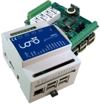
Iono Pi Max is an extremely versatile industrial server with a huge variety of Input/Output lines and standard communication interfaces, all routed to the incredibly powerful quad-core processor of the Raspberry Pi.
This driver provides support for a local installation of HSYCO on Iono Pi Max itself.
Contents
HSYCO Configuration
Add a IONO Pi Max I/O Server in the I/O Servers section of the Settings and set its parameters:
Note that the IONO Pi Max I/O Server doesn't count in the I/O servers license total, so you don't need an extra I/O Server license to use IONO Pi Max with HSYCO.
Communication
- IP Address: the IP address assigned to Iono Pi, leave blank for a local installation;
- Port: TCP port configured on Iono Pi, leave blank for a local installation;
High Availability
- Shutdown when inactive: defaults to false.
Options
| ID | Default | Values | Description |
|---|---|---|---|
| startupevents | false | true | generate IO events also during the driver’s start-up phase |
| false | start generating events only after HSYCO is aligned with the current status of the system | ||
| pollinterval | 250 | 10 <= n <= 30000 | the data acquisition interval, in milliseconds |
Datapoints
| ID | Value | R/W | Description |
|---|---|---|---|
| connection | online | R | connection established |
| offline | R | HSYCO can't connect to the device | |
| driverstate | init | R | Sfera driver is initializing |
| quit | R | Sfera driver quit | |
| running | R | Sfera driver is running (normal state) | |
| led | 0 | R | LED L1 is off |
| W | turn LED L1 off | ||
| 1 | R | LED L1 is on | |
| W | turn LED L1 on | ||
| o<1-4> | 0 | R | relay <1-4> is off |
| W | switch off relay <1-4> | ||
| 1 | R | relay <1-4> is on | |
| W | switch on relay <1-4> | ||
| oc<1-3> | 0 | R | open collector output <1-3> is off (not grounded) |
| W | switch off open collector output <1-3> | ||
| 1 | R | open collector output <1-3> is on (grounded) | |
| W | switch on open collector output <1-3> | ||
| di<1-6> | 0 | R | digital input <1-6> is low |
| 1 | R | digital input <1-6> is high | |
| ai<1-4> | <val> | R | analog input <1-4> is reading a voltage equal to <val> (in Volts) |
| wiegand.<1-2> | <val> | R | if option "wiegandbits" set to false. Value as an unsigned integer in base 16 (hex) read on the specified Wiegand interface (e.g. "2c646a2") |
| <bits>/<val> | R | if option "wiegandbits" set to true. Number of bits and value (hex) read on the specified Wiegand interface (e.g. "26/2c646a2") | |
| onewire.bus.<id> | <val> | R | 1-Wire device <id> value |
User Interface
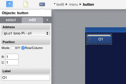
To control a digital output (O1 ... O4, OC1 ... OC3, LED), add a button or a buttonicon object to your project page and set its address field to the corresponding datapoint:
Release Notes
3.7.0
- initial release
Iono Pi Max is a registered trademark of Sfera Labs Srl

