Difference between revisions of "Alert5 (I/O Server Object)"
| (3 intermediate revisions by the same user not shown) | |||
| Line 11: | Line 11: | ||
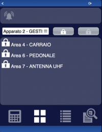
The second image shows all areas associated to the selected system, you can arm/disarm every single area. You can also arm/disarm alla areas of the selected system together. | The second image shows all areas associated to the selected system, you can arm/disarm every single area. You can also arm/disarm alla areas of the selected system together. | ||
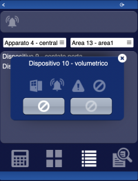
| − | The third image shows all devices associated to the selected system and area, you can bypass/unbypass | + | The third image shows all devices associated to the selected system and area, you can activate or bypass/unbypass the device. The four icons inside device popup represents in order: state(open/closed or active/inactive), alarm, fault, bypass. |
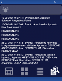
The fourth image shows the most recent logs of Alert5 system. | The fourth image shows the most recent logs of Alert5 system. | ||
| Line 17: | Line 17: | ||
The icon on top of the page will turn white when an area is in alarm. | The icon on top of the page will turn white when an area is in alarm. | ||
| − | The ( | + | The (alert5) object is listed in the Project Editor’s new object list only when at least one Alert5 I/O Server is defined |
<noinclude> | <noinclude> | ||
For further details refer to the [[Alert5 | Alert5 I/O Server Application Note]]. | For further details refer to the [[Alert5 | Alert5 I/O Server Application Note]]. | ||
| Line 26: | Line 26: | ||
<includeonly>==</includeonly>== Syntax ==<includeonly>==</includeonly> | <includeonly>==</includeonly>== Syntax ==<includeonly>==</includeonly> | ||
| − | ( | + | (alert5 <server id>; <position>) |
E.g. | E.g. | ||
| − | ( | + | (alert5 xgen; x10y20) |
Latest revision as of 15:52, 6 October 2021
The user interface for the Alert5 system:
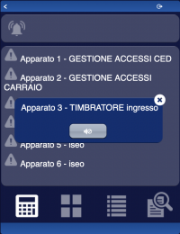
The first image shows the list of configured systems, you can reset the alarm for every single system.
The second image shows all areas associated to the selected system, you can arm/disarm every single area. You can also arm/disarm alla areas of the selected system together.
The third image shows all devices associated to the selected system and area, you can activate or bypass/unbypass the device. The four icons inside device popup represents in order: state(open/closed or active/inactive), alarm, fault, bypass.
The fourth image shows the most recent logs of Alert5 system.
The icon on top of the page will turn white when an area is in alarm.
The (alert5) object is listed in the Project Editor’s new object list only when at least one Alert5 I/O Server is defined
For further details refer to the Alert5 I/O Server Application Note.
Parameters
- server id: the server ID. Supports Redirect variables
- position: the object's position. Use the pixels or rows and columns coordinates format
Syntax
(alert5 <server id>; <position>)
E.g.
(alert5 xgen; x10y20)


