Domino
The DOMINO system is DUEMMEGI’s proprietary bus architecture for home automation. HSYCO fully integrates with this system through the DFCP control and gateway module, and its FXP-XT serial communication protocol. A serial connection between the DFCP and the HSYCO SERVER is required for the integration, either directly through the server’s RS-232 port or via the RS-232 port of a supported serial to IP gateway, including the WEBS module.
Contents
Communication
Employ a DE-9 (often called DB-9) male-female RS-232 straight cable to connect the RS-232 DFCP port to the serial port on HSYCO SERVER or serial gateway. The communication baud rate can be set to 9600, 38400, 57600 or 115200 bps, according to the DFCP serial port settings. The protocol requires 8bit data, no parity, one stop bit, no flow control. A speed of 115200 bps is recommended to achieve good performance, particularly when the number of devices connected to the bus is large.
HSYCO Configuration
Options
| ID | Default | Values | Description |
|---|---|---|---|
| startupevents | false | true | generate IO events also during the driver’s start-up phase |
| false | start generating events only after HSYCO is aligned with the current status of the system | ||
| inputdiscovery | false | true | auto-detects DOMINO’s input devices as configured in the DFCP, and automatically creates the list of all detected devices and individual data points in the systemtopo.txt file. Should be enabled to allow the automatic update of (button) objects’ states |
| false | auto-detect for input devices is disabled | ||
| outputdiscovery | true | true | auto-detects DOMINO’s output devices as configured in the DFCP, and automatically creates the list of all detected devices and individual data points in the systemtopo.txt file. Should be enabled to allow the automatic update of (button) objects’ states |
| false | auto-detect for output devices is disabled | ||
| virtualdiscovery | false | true | auto-detects DOMINO’s virtual points for input and output devices as configured in the DFCP, and automatically creates the list of all detected virtual data points in the systemtopo.txt file. Should be enabled to allow the automatic update of (button) objects’ states |
| false | auto-detect for devices’ virtual data points is disabled | ||
| virtualpoints | false | 1...2033 | enables polling for the first n virtual points of the DFCP. Enable this option only if you need to generate I/O events based on these virtual points |
| true | enables polling for all the 2032 virtual points of the DFCP | ||
| false | polling of the DFCP virtual data points is disabled | ||
| registers | false | 1...1024 | enables polling for registers R0-Rn of the DFCP. Enable this option only if you need to generate I/O events based on these registers |
| true | enables polling for registers R0-R127 of the DFCP | ||
| false | polling of the DFCP registers is disabled | ||
| powerdisplay | false | true | enables polling for registers R0-Rn of the DFCP. Enable this option only if you need to generate I/O events based on these registers |
| ≥ 0 (DFANA address) | enables the automatic display in the GUI of the total real power measured by a DFANA module connected to this DFCP. Note that, if you have more than one DFCP gateway, you should enable this option for one gateway only | ||
| false | power display disabled for this DFCP | ||
| powersensivity | 50 | ≥ 0 | measured power changes are reported only if the difference from last reading is equal or greater than the power sensivity option, in Watts |
| powerinterval | 1 | ≥ 0 | power polling interval for the DFCC meter, in seconds |
| detectevents | false | true | generate forced events when a device is detected at start-up |
| false | do not generate events when a device is detected at start-up | ||
| toolspassword | string | set this option with a long string (only letters and numbers) password to allow the remote connection of DFCP-IDE and other configuration tools to the DFCP gateways that are connected to HSYCO. For additional security, it is recommended to set this option only when required | |
| language | english | en it fr | language for all messages from the DOMINO system: English, Italian or French |
The Device Configuration Database
The systemtopo.txt file contains the list of all devices and their individual input, output and virtual data points that could be directly associated to graphic object in the Web-based user interface. This file can be filled manually or automatically by HSYCO at start-up. To enable automatic discovery and automatic generation of devices’ information in the systemtopo file, use the inputdiscovery, outputdiscovery and virtualdiscovery options in the hsyco.ini configuration file. The default behavior is to only discover devices with output data points.
This is an example of an automatically generated systemtopo.txt file:
(devices)
domino.o10.1 : LIGHT ; LIGHT
domino.o6.1 : LIGHT ; DIMMER
domino.o7.2 : LIGHT ; LIGHT
domino.o7.1 : LIGHT ; DIMMER
domino.o9.2 : AUTOM ; VSHUT
domino.o5.4 : LIGHT ; LIGHT
domino.o9.1 : AUTOM ; VSHUT
domino.o5.3 : LIGHT ; LIGHT
domino.o5.2 : LIGHT ; LIGHT
domino.o5.1 : LIGHT ; LIGHT
You should then manually add comments and other optional parameters:
(devices)
domino.o10.1 : LIGHT ; LIGHT; main entrance light
domino.o6.1 : LIGHT ; DIMMER; lobby dimmer
domino.o7.2 : LIGHT ; LIGHT; kitchen workbench
domino.o7.1 : LIGHT ; DIMMER; kitchen main dimmer
DFCP Virtual Data Points and Registers
The DFCP implements 2032 virtual points for binary (on/off) data and 1024 registers for positive scalar values (0-65535). All the virtual points and the registers can optionally generate I/O events. You can also write to the virtual data points and registers using the IO action in EVENTS or ioSet() method in Java. You cannot directly control the DFCP virtual data points and registers using GUI objects. To enable polling of the current state of the DFCP’s virtual data points, enable the virtualpoints options in hsyco.ini. To enable polling of the current state of the DFCP’s registers, enable the registers options in hsyco.ini. If you only have to write to virtual points or registers, enabling polling is not strictly required.
| ID | Value | R/W | Description |
|---|---|---|---|
| v0.<n> | 0 | RW | virtual data point <n> off (<n>: 1-2032) |
| 1 | RW | virtual data point <n> on (<n>: 1-2032) | |
| r0.<n> | <x> | RW | register <n> off (<n>: 0-1023) set to value <x> (<x>: 0-65535) |
DFCP Internal Clock
The DFCP module has an integrated real-time clock. You can use the clock datapoint to read the DFCP date and time, and set the DFCP clock to HSYCO’s current time.
| ID | Value | R/W | Description |
|---|---|---|---|
| clock | yyyy-mm-dd hh:mm:ss | R | the DFCP clock current time |
| read | W | read the DFCP clock, and the delta with HSYCO’s time | |
| sync | W | set the DFCP clock to HSYCO’s current time | |
| clock.delta | integer number | R | the delta time in seconds between the DFCP and HSYCO clocks. A positive number means that the DFCP clock is ahead of HSYCO |
DOMINO Modules Events and Control
| Module Code | Description |
|---|---|
| DF4I | 4 digital inputs |
| DFCK3 | clock |
| DF8I | 2x4 digital inputs |
| DF2R | 2 outputs (relay) |
| DF4R, DF4RP | 4 outputs (power relay) |
| DF4RP/I | 4 generic inputs ON-OFF + 4 outputs |
| DFDI, DFDI2, DFDI2B, DFDM, DFDT | 1 output (dimmer) |
| DFDMX | DMX interface |
| DFDALI | DALI interface |
| DFDV | 1 output (1-10V - ballast) + 1 output (power relay) |
| DFTP | 2 outputs (shutters) |
| DFTP/I | 2 outputs (shutters) + 4 digital inputs |
| DFTR | 2 outputs (shutters) + 1 output (relay) |
| DF4IL | 4 digital inputs + 4 outputs (LED) |
| DF8IL | 8 digital inputs + 8 outputs (LED) |
| DFAI | 2 analog inputs |
| DFLUX, DFSUN | light sensor |
| DFCT/DFTZ | temperature sensor |
| DFRHT | temperature and humidity sensor |
| DFMETEO | weather module |
| DFCC | electric energy meter and load manager |
Datapoints
DF4I
The DF4I is an input module with 4 digital inputs. It uses one address in the DOMINO bus.
| ID | Value | R/W | Description |
|---|---|---|---|
| i.<address>.1 | 0 | R | input pin 1 off |
| 1 | R | input pin 1 on | |
| i.<address>.2 | 0 | R | input pin 2 off |
| 1 | R | input pin 2 on | |
| i.<address>.3 | 0 | R | input pin 3 off |
| 1 | R | input pin 3 on | |
| i.<address>.4 | 0 | R | input pin 4 off |
| 1 | R | input pin 4 on |
DFCK3
The DFCK3 is an input module for managing up to 15 different zones with an integrated clock. It uses one address in the DOMINO bus.
| ID | Value | R/W | Description |
|---|---|---|---|
| i.<address>.1 | 0 | R | input pin 1 off |
| 1 | R | input pin 1 on | |
| i.<address>.2 | 0 | R | input pin 2 off |
| 1 | R | input pin 2 on | |
| i.<address>.3 | 0 | R | input pin 3 off |
| 1 | R | input pin 3 on | |
| i.<address>.4 | 0 | R | input pin 4 off |
| 1 | R | input pin 4 on | |
| i.<address>.5 | 0 | R | input pin 5 off |
| 1 | R | input pin 5 on | |
| i.<address>.6 | 0 | R | input pin 6 off |
| 1 | R | input pin 6 on | |
| i.<address>.7 | 0 | R | input pin 7 off |
| 1 | R | input pin 7 on | |
| i.<address>.8 | 0 | R | input pin 8 off |
| 1 | R | input pin 8 on | |
| i.<address>.9 | 0 | R | input pin 9 off |
| 1 | R | input pin 9 on | |
| i.<address>.10 | 0 | R | input pin 10 off |
| 1 | R | input pin 10 on | |
| i.<address>.11 | 0 | R | input pin 11 off |
| 1 | R | input pin 11 on | |
| i.<address>.12 | 0 | R | input pin 12 off |
| 1 | R | input pin 12 on | |
| i.<address>.13 | 0 | R | input pin 13 off |
| 1 | R | input pin 13 on | |
| i.<address>.14 | 0 | R | input pin 14 off |
| 1 | R | input pin 14 on | |
| i.<address>.15 | 0 | R | input pin 15 off |
| 1 | R | input pin 15 on |
DF8I
The DF8I is an input module with 2x4 digital inputs. It uses two consecutive addresses in the DOMINO bus.
| ID | Value | R/W | Description |
|---|---|---|---|
| i.<address>.1 | 0 | R | input pin 1 off |
| 1 | R | input pin 1 on | |
| i.<address>.2 | 0 | R | input pin 2 off |
| 1 | R | input pin 2 on | |
| i.<address>.3 | 0 | R | input pin 3 off |
| 1 | R | input pin 3 on | |
| i.<address>.4 | 0 | R | input pin 4 off |
| 1 | R | input pin 4 on | |
| i.<address+1>.1 | 0 | R | input pin 1 off |
| 1 | R | input pin 1 on | |
| i.<address+1>.2 | 0 | R | input pin 2 off |
| 1 | R | input pin 2 on | |
| i.<address+1>.3 | 0 | R | input pin 3 off |
| 1 | R | input pin 3 on | |
| i.<address+1>.4 | 0 | R | input pin 4 off |
| 1 | R | input pin 4 on |
DF2R
The DF2R is an output module with 2 relay outputs. It uses one address in the DOMINO bus.
| ID | Value | R/W | Description |
|---|---|---|---|
| o.<address>.1 | 0 off |
RW | output pin 1 off |
| 1 on |
RW | output pin 1 on | |
| o.<address>.2 | 0 off |
RW | output pin 2 off |
| 1 on |
RW | output pin 2 on |
DF4R, DF4RP
The DF4R (DF4RP) is an output module with 4 relay outputs. It uses one address in the DOMINO bus.
| ID | Value | R/W | Description |
|---|---|---|---|
| o.<address>.1 | 0 off |
RW | output pin 1 off |
| 1 on |
RW | output pin 1 on | |
| o.<address>.2 | 0 off |
RW | output pin 2 off |
| 1 on |
RW | output pin 2 on | |
| o.<address>.3 | 0 off |
RW | output pin 3 off |
| 1 on |
RW | output pin 3 on | |
| o.<address>.4 | 0 off |
RW | output pin 4 off |
| 1 on |
RW | output pin 4 on |
DF4RP/I
The DF4RP/I is an output module with 4 generic inputs and 4 relay outputs. It uses one input address and one output address in the DOMINO bus.
| ID | Value | R/W | Description |
|---|---|---|---|
| i.<address>.1 | 0 | R | input pin 1 off |
| 1 | R | input pin 1 on | |
| o.<address>.1 | 0 | RW | output pin 1 off |
| 1 | RW | output pin 1 on | |
| i.<address>.2 | 0 | R | input pin 2 off |
| 1 | R | input pin 2 on | |
| o.<address>.2 | 0 | RW | output pin 2 off |
| 1 | RW | output pin 2 on | |
| i.<address>.3 | 0 | R | input pin 3 off |
| 1 | R | input pin 3 on | |
| o.<address>.3 | 0 | RW | output pin 3 off |
| 1 | RW | output pin 3 on | |
| i.<address>.4 | 0 | R | input pin 4 off |
| 1 | R | input pin 4 on | |
| o.<address>.4 | 0 | RW | output pin 4 off |
| 1 | RW | output pin 4 on |
DFDM, DFDI, DFDI2, DFDI2B, DFDT
The DFDM, DFDI, DFDI2, DFDI2B and DFDT are output modules with 1 dimmer output. They use one address in the DOMINO bus.
| ID | Value | R/W | Description |
|---|---|---|---|
| o.<address> | program | R | program mode |
| fault | R | dimmer fault | |
| auto | R | auto mode | |
| man | R | manual mode | |
| o.<address>.1 | off | RW | dimmer off |
| 1...100% | RW | percent dimmer level | |
| on | RW | dimmer on at last level | |
| o.<address>.ramp | save | RW | saves the current ramp as default |
| 1...30 | RW | ramp value in seconds (1 sec steps up to 10 and 2 sec steps up to 30) | |
| 40, 50, 60 | RW | ramp value in seconds (10 sec steps) |
Datapoints
| ID | Value | R/W | Description |
|---|---|---|---|
| connection | online | R | connection established |
| offline | R | HSYCO can't connect to the panel |
User Interface
Object
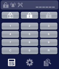
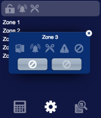
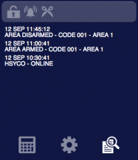
The user interface for the control and supervision of one area of the system, the zones and the visualization of the security log:
The Inim object is listed in the Project Editor’s new object list only when at least one INIM I/O Server is defined.
Parameters
- id - the id assigned to the INIM I/O Server in hsyco.ini. Supports Redirect variables
- area - the number of the area to be addressed. Supports Redirect variables
- pos - the object’s position. Use the pixels or rows and columns coordinates format.
Syntax
(inim <server id>; <area>; <position>)
E.g.
(inim serverid; area; x10y20)
UISET Actions
| ID | Attribute | Set to | |
|---|---|---|---|
USER Commands
| Name | Param | Action |
|---|


