Inim
Inim SmartLiving panels are multi-area intrusion detection systems. The integration with HSYCO can be accomplished via direct control through the RS-232 port on the board.
Contents
Communication
Employ a female-female RS-232 crossed cable to connect the panel directly to HSYCO or to an Ethernet/RS-232 gateway.
RS-232 parameters:
| Baud rate | 57600 |
| Data bits | 8 |
| Stop bit | 1 |
| Parity | none |
| Flow control | none |
HSYCO Configuration
Options
| ID | Default | Values | Description |
|---|---|---|---|
| gui | true | true | enable support for the UI object, UISET actions and USER commands |
| false | disable UI support | ||
| startupevents | false | true | generate IO events also during the driver’s start-up phase |
| false | start generating events only after HSYCO is aligned with the current status of the system | ||
| logsize | 50 | n ≥ 0 | the number of log lines to display in the UI object |
| pollinterval | 4 | n > 0 | the data acquisition interval, in seconds |
| mod | 515 | the panel model to control. This option is required | |
| 1050 | |||
| 10100 | |||
| pin | <code> | use the specified user code to perform operations that require user authentication. If this option is not specified it will be required to manually insert the pin every time such operations are performed |
inim.ini
The inim.ini file is a specific configuration file located in the root directory.
This file is required to provide the I/O Server with the mapping between the board terminals and the respective zones or outputs when a configuration different from the default one is used.
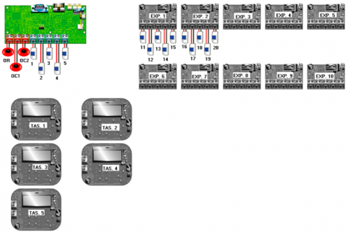
The default configuration for the SmartLiving 515 is shown in the following diagram:
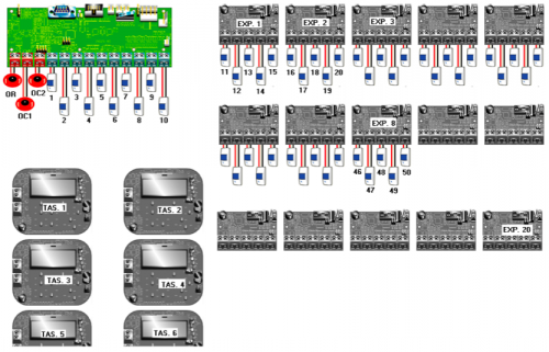
And here is default configuration for SmartLiving 1050 and 10100 (for the 10100 model this diagram must be extended to 100 terminals and 40 expanders):
If the inim.ini file is not created or it does not contain specifications for our I/O server, then the above configurations are used.
If, on the other hand, you are using a custom configuration, then, for each used terminal of the panel, expanders, and keypads you must specify its configuration.
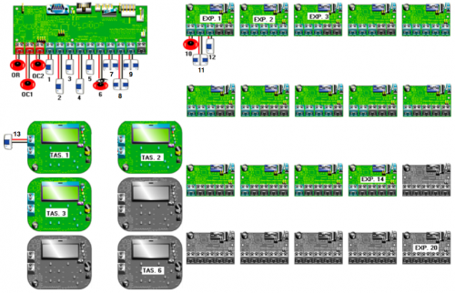
For instance, consider the following configuration on a SmartLiving1050:
The corresponding configuration in inim.ini, assuming that the ID of the I/O Server is "inm", would be the following:
inm.t1 = z1
inm.t2 = z2
inm.t3 = z3
inm.t4 = z4
inm.t5 = z5
inm.t6 = z6,o6
inm.t7 = z7d
inm.t8 = z8d
inm.t9 = z9d

inm.e1.t1 = o10
inm.e1.t2 = z11d
inm.e1.t3 = o12

inm.k1.t1 = z13
Terminals on the panel itself are referred to using the notation “<ioserver_id>.t<n>” where <n> is the number of the board terminal from left to right. Terminals on expanders are identified by the string “<ioserver_id>.e<m>.t<n>” where <m> is the expander number and <n> the terminal number on the expander board. Finally, the syntax “<ioserver_id>.k<m>.t<n>” is used to identify terminals on keyboards.
When a terminal is configured as a simple zone (![]() ), it should be assigned the corresponding zone number (e.g. "
), it should be assigned the corresponding zone number (e.g. "= z1").
If the terminal is configured as double zone (![]() ) then append “d” to the zone id (e.g. "
) then append “d” to the zone id (e.g. "= z7d"). This configuration allows to have two zones connected to the same terminal, thus the I/O Server will handle these two zones independently: the notation "z<n>" will identify datapoints related to base zones, while "z<n>d" identifies double zones.
If the terminal correspond to an output (![]() ) specify the corresponding output number (e.g. "
) specify the corresponding output number (e.g. "= o10"), while if the terminal is configured as an IO (![]() ) then it will be seen as a zone as well as an output, so specify both of them (e.g. "
) then it will be seen as a zone as well as an output, so specify both of them (e.g. "= z6,o6").
Further, it is possible to assign a name to a zone terminal to be displayed in the user interface by adding it at the end of the line after an additional “=”. For instance:
inm.t4 = z4 = door
inm.t5 = z5 = corridor
inm.t6 = z6, o6 = alarm point
inm.e1.t2 = z11d = room 1, room 2
As you can see from the last line, when referring to a double zone you can specify two different names separated by a comma.
N.B. SmartLiving 515 panels have only 5 terminals on the board and the indexing of zones and outputs skips the numbers from 6 to 10 as we can see from the image above. But, from tests conducted on different configurations, sometimes these indexes are actually used, thus refinements on the configuration in inim.ini must be applied to map the terminals with the correct zone or output number.
Datapoints
| ID | Value | R/W | Description |
|---|---|---|---|
| connection | online | R | connection established |
| offline | R | HSYCO can't connect to the panel | |
| armed | 0 | R | all groups are disarmed |
| W | disarm all groups | ||
| 1 | R | the system is (partially) armed | |
| W | arm all groups | ||
| alarm | 0 | R | the system is not in a alarm state |
| 1 | R | the system is in a alarm state | |
| tamper | 0 | R | the system is not in a tamper state |
| 1 | R | the system is in a tamper state | |
| panel.tamper | 0 | R | the panel is not tampered |
| 1 | R | the panel is tampered | |
| bell.tamper | 0 | R | the bell is not tampered |
| 1 | R | the bell is tampered | |
| low.volts | 0 | R | voltage ok |
| 1 | R | low voltage detected | |
| sounder | 0 | R | the sounder is inactive |
| 1 | R | the sounder is active | |
| audio | 0 | R | the audio signal of the panel is inactive |
| 1 | R | the audio signal of the panel is active | |
| strobe | 0 | R | the strobe is inactive |
| 1 | R | the strobe is active | |
| mains.fail | 0 | R | no mains fail |
| 1 | R | mains fail | |
| power.fail | 0 | R | no power fail |
| 1 | R | power fail | |
| battery.fail | 0 | R | no battery fail |
| 1 | R | battery fail | |
| fuse.1.fault | 0 | R | fuse 1 is working |
| 1 | R | fuse 1 in fault | |
| fuse.2.fault | 0 | R | fuse 2 is working |
| 1 | R | fuse 2 in fault | |
| fuse.3.fault | 0 | R | fuse 3 is working |
| 1 | R | fuse 3 in fault | |
| line.fault | 0 | R | communication line is working |
| 1 | R | communication line in fault | |
| c<n>.name | <text> | R | the name of circuit <n> is set to <text> |
| g<n>.name | <text> | R | the name of group <n> is set to <text> |
| g<n>.armed | 0 | R | group <n> is disarmed |
| W | disarm group <n> | ||
| 1 | R | group <n> is armed | |
| W | arm group <n> | ||
| c<n>.alarm | 0 | R | circuit <n> is not in alarm state |
| 1 | R | circuit <n> is in alarm state | |
| c<n>.tamper.alarm | 0 | R | circuit <n> is not in tamper alarm |
| 1 | R | circuit <n> is in tamper alarm | |
| c<n>.open | 0 | R | circuit <n> is closed |
| 1 | R | circuit <n> is open | |
| c<n>.tamper | 0 | R | circuit <n> is not tampered |
| 1 | R | circuit <n> is tampered | |
| c<n>.fault | 0 | R | circuit <n> is working properly |
| 1 | R | circuit <n> is faulty | |
| c<n>.bypassed | 0 | R | circuit <n> is not bypassed |
| W | unbypass circuit <n> | ||
| 1 | R | circuit <n> is bypassed | |
| W | bypass circuit <n> | ||
| c<n>.isolated | 0 | R | circuit <n> is not isolated |
| W | un-isolate circuit <n> | ||
| 1 | R | circuit <n> is isolated | |
| W | isolate circuit <n> | ||
| c<n>.soaked | 0 | R | circuit <n> is not soaked |
| W | un-soak circuit <n> | ||
| 1 | R | circuit <n> is soaked | |
| W | soak circuit <n> | ||
| c<n>.status | <status_values> | R | the status of circuit <n> is set to the reported values |
| c<n>.attributes | <attributes_values> | R | the attributes of circuit <n> are set to the reported values |
| c<n>.resistance | <value> | R | the measured resistance on circuit <n> is <value> ohm |
| >20k | R | the measured resistance on circuit <n> is greater than 20 K-ohm | |
| k<n>.tamper | 0 | R | keypad <n> is not tampered |
| 1 | R | keypad <n> is tampered | |
| k<n>.fault | 0 | R | keypad <n> is working properly |
| 1 | R | keypad <n> is faulty | |
| logon.<n> | <user_num> | R | user with number <user_num> logged in from keypad <n> |
| error | R | wrong pin entered in keypad <n> | |
| system | reset | W | reset alarms |
| Circuit status values | |
|---|---|
| Value | Description |
| A | alarm/open |
| B | alarm/open and tamper |
| E | latched alarm and tamper |
| M | marginal clear |
| m | marginal alarm |
| N | normal |
| T | tamper |
| L | latched alarm |
| F | fault/no answer |
| X | Auxiliary alarm |
| Circuit attributes values | |
|---|---|
| Value | Description |
| B | bypassed circuit |
| I | isolated circuit |
| S | soak failed |
| T | soaked circuit |
| Y | temporarily bypassed circuit |
| Q | temporarily isolated circuit |
| H | circuit in shunt |
| A | existing circuit |
| M | multi-alarm |
| F | bank reset failed/door forced |
| L | locked |
| O | open |
Attributes can be combined together, for instance if a circuit is both isolated and bypassed, the attribute value will be “BI”.
User Interface
Guardall Object
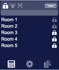
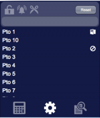
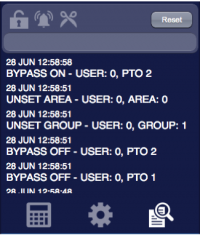
The user interface for the Guardall multi-area intrusion detection system:
The Guardall object is listed in the Project Editor’s new object list only when at least one Guardall I/O Server is defined.
Parameters
- server id: the server ID. Supports Redirect variables
- position: the object's position. Use the pixels or rows and columns coordinates format
Syntax
(guardall <server id>; <position>)
E.g.
(guardall serverid; x10y20)
UISET Actions
| ID | Attribute | Set to | |
|---|---|---|---|
| log | value | latest security log lines (as many as specified by the 'logsize' option) | |
| log0 | value | latest line of the security log when a new entry is added, set back to blank after a short period | |
| c<n>.name | value | name assigned to circuit <n> or its number if no name is defined | |
| connection.label | visible | true | when datapoint connection = offline |
| false | when datapoint connection = online | ||
| <datapoint_id>.label.1 | visible | true | when datapoint with ID <datapoint_id> has value '1' |
| false | when datapoint with ID <datapoint_id> has value '0' | ||
| <datapoint_id>.label.0 | visible | true | when datapoint with ID <datapoint_id> has value '0' |
| false | when datapoint with ID <datapoint_id> has value '1' | ||
USER Commands
| Name | Param | Action |
|---|---|---|
| armed | 0 | disarm all groups |
| 1 | arm all groups | |
| g<n>.armed | 0 | disarm group <n> |
| 1 | arm group <n> | |
| c<n>.bypassed | 0 | unbypass zone <n> |
| 1 | bypass zone <n> | |
| c<n>.isolated | 0 | un-isolate zone <n> |
| 1 | isolate zone <n> | |
| c<n>.soaked | 0 | un-soak zone <n> |
| 1 | soak zone <n> | |
| system | reset | reset alarms |
