Boschfpa
The BOSCH FPA-5000 is a modular fire panel system.
Contents
Communication
Be sure to use BOSCH sofware management tool RPS version 4_0_11 or later for the FPA configuration.
Configure the RS232 Communication Module module as follows:
After the upload configuration process the FPA-5000 is ready to be connected via RS232.
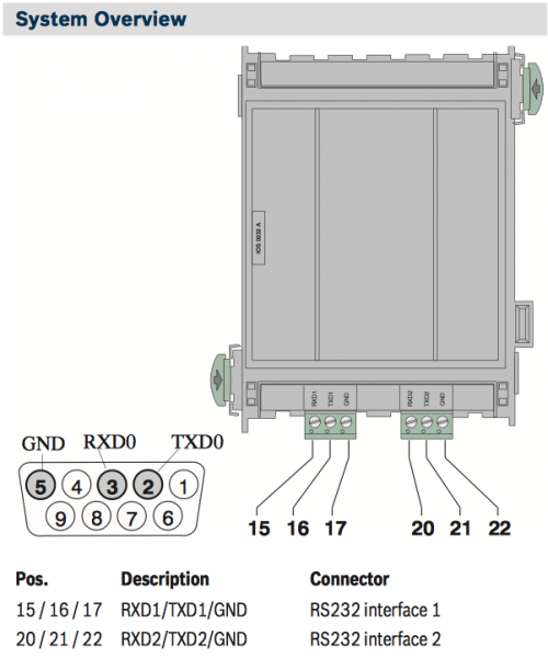
RS232 Communication Module overview:
RS-232 parameters:
| Baud rate | 9600 |
| Data bits | 7 |
| Stop bit | 1 |
| Parity | even |
| Flow control | none |
HSYCO Configuration
Add a BOSCHFPA I/O Server in the I/O Servers section of the Settings and set its parameters:
Communication
- Comm ID: select the comm port connected to the panel.
High Availability
- Shutdown when inactive: defaults to true.
Options
| ID | Default | Values | Description |
|---|---|---|---|
| gui | true | true | enable support for the UI (event log object) |
| false | disable UI support | ||
| language | system language | en | language of log and display messages. Supported values are English, Italian and German |
| it | |||
| de | |||
| logsize | 100 | n ≥ 0 | the number of log lines to display in the UI object |
boschfpa.ini
The boschfpa.ini file is an optional configuration file located in the main directory (same directory as hsyco.ini or hsyco.jar) and used to define zones (lines) names. If defined, these names will be used instead of the original numbers in the log files and GUI event log object.
Changes to the boschfpa.ini file are automatically detected and don't require a restart to become effective.
![]() This file is case sensitive.
This file is case sensitive.
For each zone (line), enter a line formatted as:
<io_server_id>.line.<logical address>.<subaddress> = <name>
For instance:
fpa.line.3.1 = DATA ROOM SENSOR
fpa.line.4.1 = GENERATORS ROOM
Datapoints
| ID | Value | R/W | Description |
|---|---|---|---|
| connection | online | R | connection established |
| offline | R | HSYCO can't connect to the panel | |
| system.fault | 1 | R | general system fault |
| 0 | R | reset | |
| system.batteryfault | 1 | R | general battery fault |
| 0 | R | reset | |
| system.lowbattery | 1 | R | low battery |
| 0 | R | reset | |
| system.nobattery | 1 | R | low battery |
| 0 | R | reset | |
| system.nopower | 1 | R | general no AC power fault |
| 0 | R | reset | |
| system.tamper | 1 | R | general tamper condition (central unit, zones, modules) |
| 0 | R | reset | |
| system.radiofault | 1 | R | general radio modules fault |
| 0 | R | reset | |
| system.radiolowbattery | 1 | R | radio modules low battery |
| 0 | R | reset | |
| system.duress | 1 | R | duress status |
| 0 | R | reset | |
| system.maintenance | 1 | R | maintenance mode |
| 0 | R | reset | |
| zone.<n>.disabled | 1 | R | zone <n> disabled |
| 0 | R | zone <n> enabled | |
| zone.<n>.alarm | 1 | R | zone <n> alarm |
| 0 | R | reset | |
| zone.<n>.tamper | 1 | R | zone <n> tamper alarm |
| 0 | R | reset | |
| zone.<n> | enable | W | enable zone <n> using default code |
| disable | W | disable zone <n> using default code | |
| enable.<c> | W | enable zone <n> using code <c> | |
| disable.<c> | W | disable zone <n> using code <c> | |
| partition.<n>.armed | 1 | R | area <n> is armed (any mode) |
| 0 | R | reset | |
| partition.<n>.disarmed | 1 | R | area <n> is not armed |
| 0 | R | reset | |
| partition.<n>.away | 1 | R | area <n> away mode |
| 0 | R | reset | |
| partition.<n>.stay | 1 | R | area <n> stay mode |
| 0 | R | reset | |
| partition.<n>.staynodelay | 1 | R | area <n> stay no delay mode |
| 0 | R | reset | |
| partition.<n>.alarm | 1 | R | area <n> alarm memory |
| 0 | R | reset | |
| partition.<n> | away | W | arm area <n> using default code |
| disarm | W | disarm area <n> using default code | |
| stay | W | stay arm area <n> using default code | |
| staynodelay | W | instant stay arm area <n> using default code | |
| away.<c> | W | arm area <n> using code <c> | |
| disarm.<c> | W | disarm area <n> using code <c> | |
| stay.<c> | W | stay arm area <n> using code <c> | |
| staynodelay.<c> | W | instant stay arm area <n> using code <c> | |
| out.<n> | off | W | turn off output <n> using default code |
| on | W | turn on output <n> using default code | |
| off.<c> | W | turn off output <n> using code <c> | |
| on.<c> | W | turn on output <n> using code <c> |

